Brand: Wavgat
Type: NE555 LED Christmas Tree Decoration
EAN: Does not apply
UPC: Does not apply
MPN: Does not apply
Unit Quantity: 3 Kits
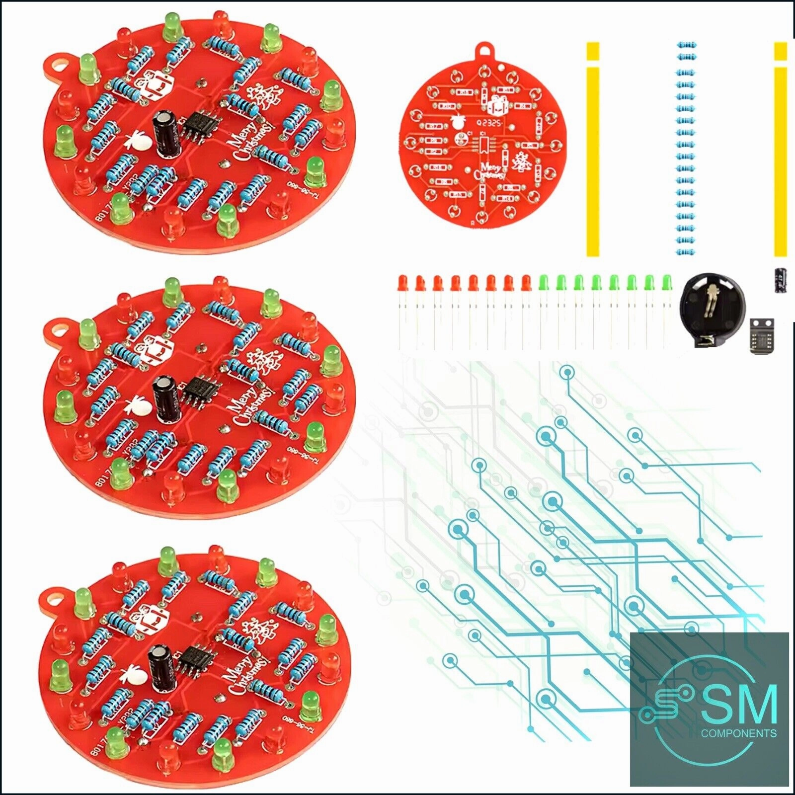
3 X NE555 LED Christmas Tree Bauble Soldering DIY Kit Red-Green LED Inc CR2032
Battery and Instructions.
Sent with Australia Post Tracked Letter
Features:
1. The product is made of high-quality materials with guaranteed quality
2. Suitable for: Christmas tree decoration, welding practice, teaching and training, and enthusiasts who like DIY
3. The product is shipped as loose parts and requires manual welding to improve one's hands-on ability
4. Lightweight and compact design of the product, it can be used anytime, anywhere
5. The product uses 1 CR2032 button battery
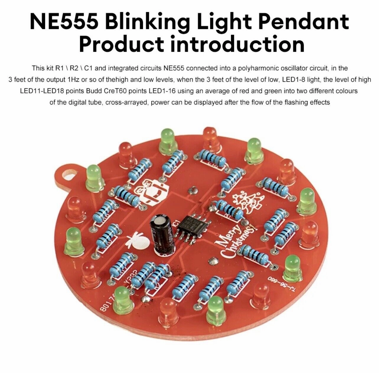
NE555 flashing light pendant product introduction:
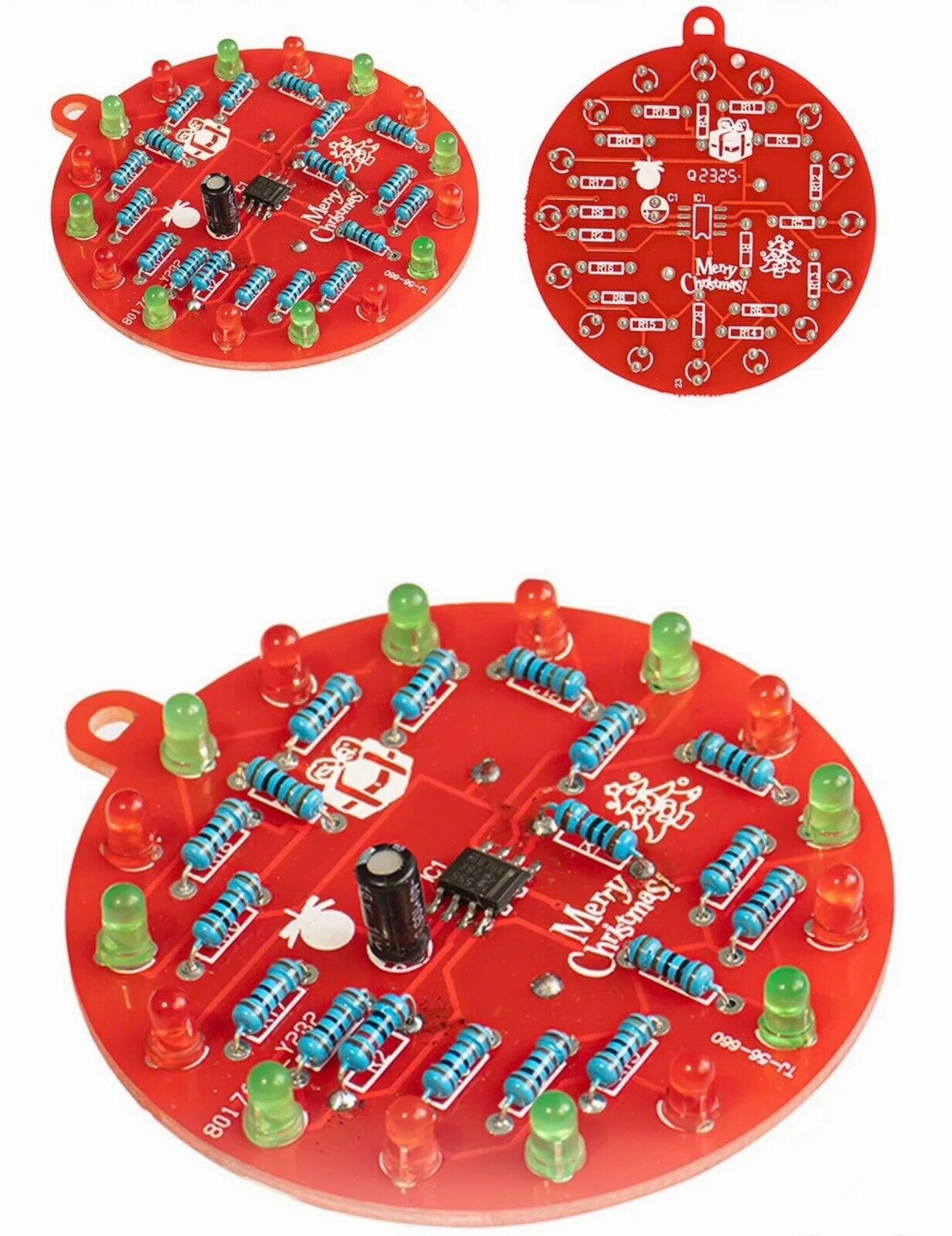
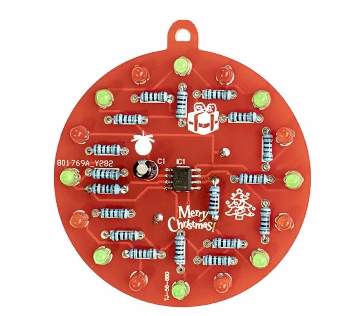
This kit R1 R2 Cl is connected to the integrated circuit NE555 to form a multi harmonic oscillation circuit. It outputs high and low levels of around 1Hz at the 3 pins. When the 3 pin level is low, LED1-8 lights up, and when the level is high, LED11-LED18 lights up. LED1-16 uses digital tubes that are evenly divided into red and green colors, arranged in a cross row. After being powered on, it can display the effect of flowing flashing.
Product Name: NE555 Flashing Lamp Hanger
Manufacturing Kit
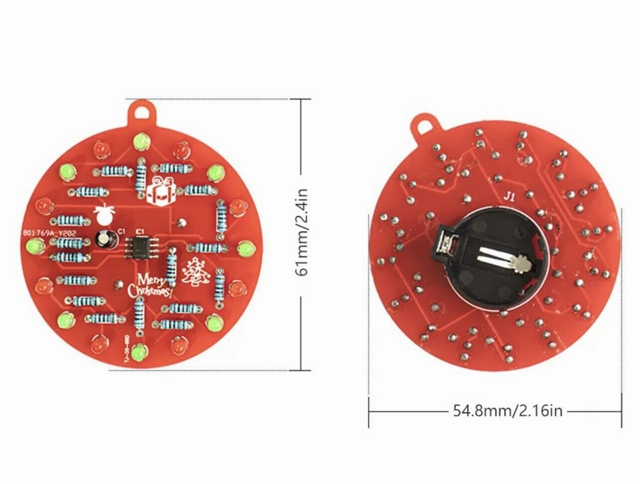
Product model: TJ-56-660
Working voltage: DC3V DC power supply (1 CR2032 button battery)
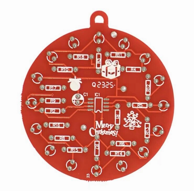
PCB board size: 61 * 54.8mm
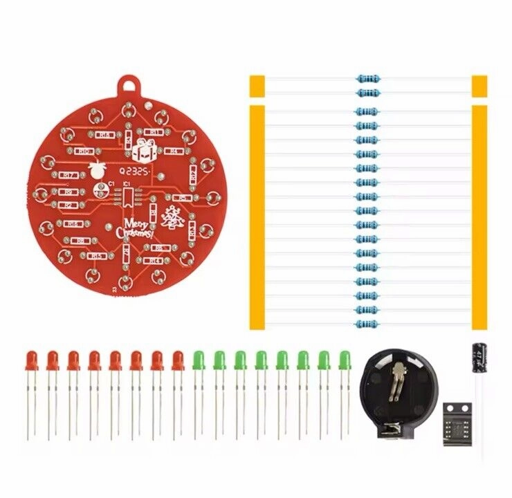
Package include:
Loose parts X1( Includes CR2032 battery)
Including Instructions
NE555 Flashing Light Pendant Instructions
2 x R1 & R2 10k Ω resistor
16 x R3-R18 510 Ω resistors
1 x IC SMD NE555
1 x 47uf capacitor
8 x LEDS all even numbers 2,4,6 etc 3MM Red Diffused
8 x LEDS all even numbers 1,3,5 etc 3MM Green Diffused
1 x Battery Holder 2032
1 x 2032 Battery
The new CR2032 will run the Bauble for approximately 30-35 hours
Welding precautions: Resistors do not distinguish between positive and negative poles, but the resistance value.
1. The colour rings of a group of 2 x 10k Ω are: brown-black-black-red-brown
2. The colour rings of 16 x 510 Ω are:
Green-brown-black-black-brown.
3. The long leg of the electrolytic capacitor is the positive pole.
4. The long leg of the light-emitting diode is the positive pole, corresponding to the hole on the edge of the board for welding.
5. The origin of the 555 chip on one corner corresponds to the notch end of the white mark on the board.
6. The battery holder corresponds
to the white mark for welding, and the side with words on the battery is exposed outside.
")

")


